A Ford F150 radio wiring harness diagram will assist you in installing new radio/stereo wires in your vehicle. It shows the setup of electrical components situated in the radio console.
My guide contains Ford F150 radio wiring harness schematics from the seventh generation to the fourteenth generation. There are also sections covering the universal aftermarket wire harness color codes and Ford wire harness color codes.
You can look forward to installing your truck’s new radio wiring DIY style. The diagrams will help you save on labor fees and make the process faster.

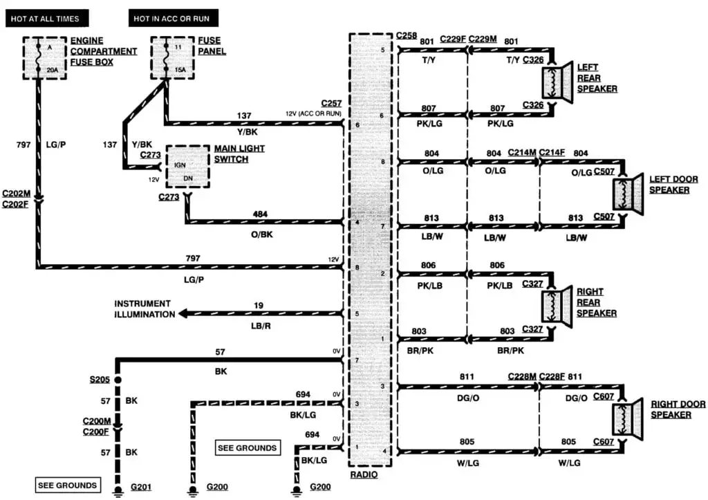
Seventh Generation Ford F150 Radio Wiring Harness Diagram (1980-1986)
This generation of radio wiring harness models is easy to install and repair. It makes use of a slightly bigger single-DIN (Deutsches Institut für Normung/German Institute for Standards) configuration. That is why the diagram appears as it does below.
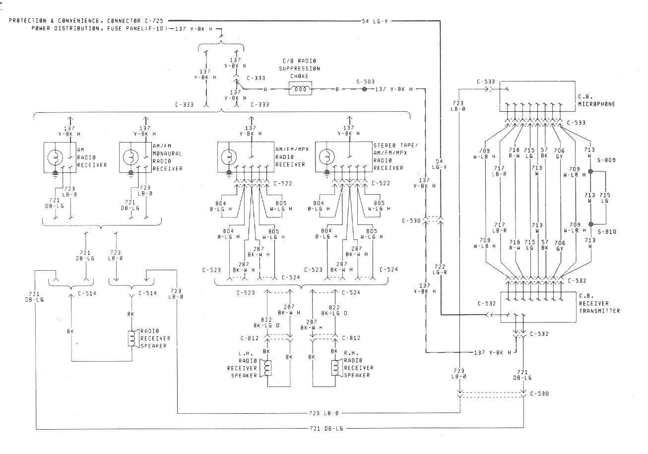
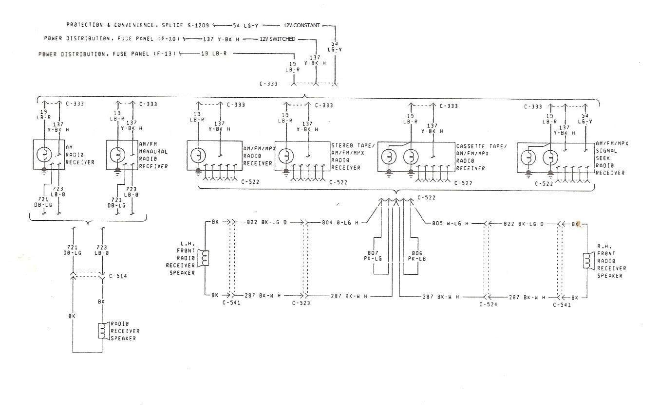
If the above diagram looks too complicated, you can just follow the wires color codes chart below:
7th Generation F150 Radio Wiring Harness Diagram (1980-1986)
| Wire Function | Wire Color |
| Constant 12V+ | Light Green |
| Switched 12V+ | Yellow/Green |
| Ground | Chassis |
| Illumination | Blue/ Brown |
| Left Front (+) | Green |
| Left Front (-) | Black/White |
| Right Front (+) | White/Red |
| Right Front (-) | Black/White |
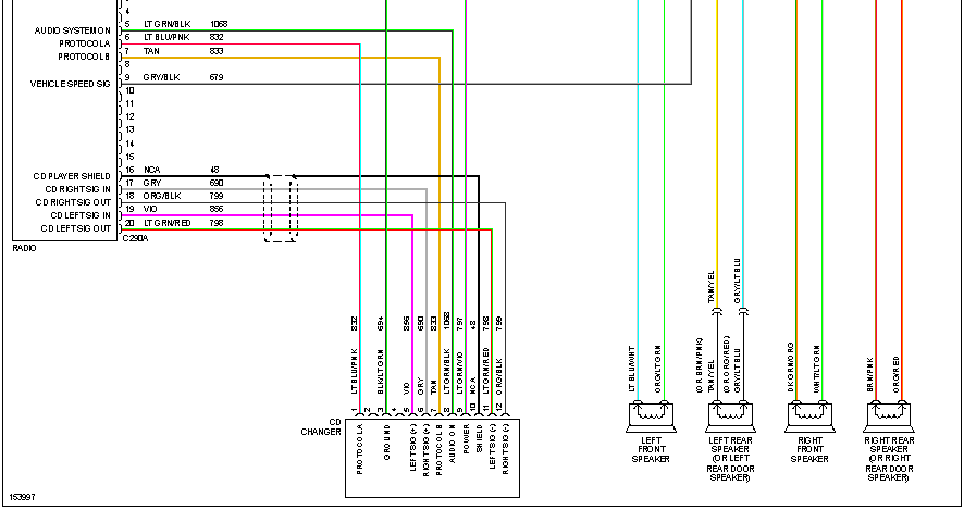
Eighth Generation Ford F150 Radio Wiring Harness Diagram (1987-1991)
The eight-generation F150 radio wiring harness diagram bears some similarities to that of the seventh generation. It shows the single DIN setup, but there is a small difference due to the F150 dash, as seen below.
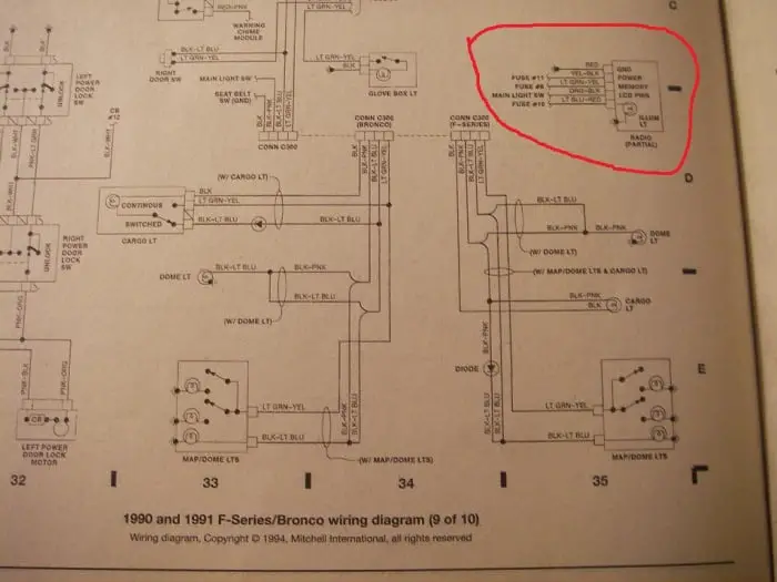
Follow the wire’s color codes below:
8th Generation F150 Radio Wiring Harness Diagram (1987-1991)
| Wire Function | Wire Color |
| Constant 12V+ | Green/Yellow |
| Switched 12V+ | Yellow/Black |
| Ground | Red/ Black |
| Illumination | Blue/Red |
| Left Front (+) | Orange/Green |
| Left Front (-) | Black/White |
| Right Front (+) | White/Green |
| Right Front (-) | Black/White |
| Left Rear (+) | Pink/Green |
| Left Rear (-) | Pink/Blue |
| Right Rear (+) | Pink/Blue |
| Right Rear (-) | Green/Orange |
Ninth Generation Ford F150 Radio Wiring Harness Diagram (1992-1996)
The ninth-generation F150 trucks were the last to have the bench-style dash feature. They were the first to start using dashboards molded around the steering column and stereo. Their stereos utilize the single-DIN configuration, which goes directly into the vehicle.
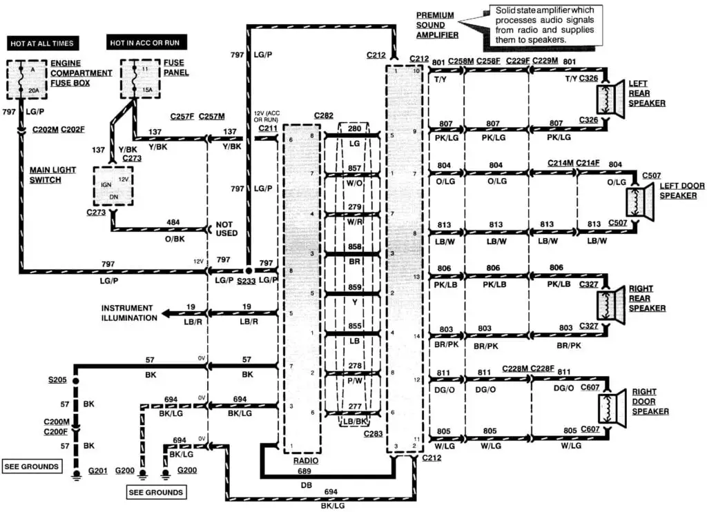
Below are the radio wiring color codes for this generation.
9th Generation F150 Radio Wiring Harness Diagram (1992-1996)
| Wire Function | Wire Color |
| Constant 12V+ | Green/Purple (1996) Green/Yellow (1992-1995) |
| Switched 12V+ | Yellow/Black |
| Ground | Black/Light Green (1996) Red or Black (1992-1995) |
| Illumination | Light Blue/Red (1996) Blue/Red (1992-1995) |
| Antenna Trigger | Blue |
| Left Front (+) | Orange/Light Green (1996) Orange/Green (1992-1995) |
| Left Front (-) | Light Blue/White (1996) Black/White (1992-1995) |
| Right Front (+) | White/Light Green (1996) White/Green (1992-1995) |
| Right Front (-) | Dark Green/Orange (1996) Black/White (1992-1995) |
| Left Rear (+) | Pink/Green (1992-1995) Gray/Light Blue (1996) |
| Left Rear (-) | Pink/Blue (1992-1995) Tan/Yellow (1996) |
| Right Rear (+) | Pink/Blue (1992-1995) Orange/Red (1996) |
| Right Rear (-) | Green/Orange (1992-1995) Brown/Pink (1996) |
Tenth Generation Ford F150 Radio Wiring Harness Diagram (1997-2003)
You can only access a tenth-generation F150 vehicle’s stereo when taking off the front paneling. The cupholder and vents must be uninstalled separately to reach the factory stereo. The stock stereo makes use of a double-DIN system, but you also need mounting kits for motorized units.
Let’s take a look at the radio wires’ color codes of this generation:
10th Generation F150 Radio Wiring Harness Diagram (1997-2003)
| Wire Function | Wire Color |
| Constant 12V+ | Green/Purple or Light Green/ Pink or Light Green/Violet |
| Switched 12V+ | Black/Pink or Black/Purple or Pink |
| Ground | Black/Green or Black/Light Green |
| Illumination | Light Blue/Red |
| Antenna Trigger | Blue |
| Left Front (+) | Gray/Light Blue |
| Left Front (-) | Tan/Yellow |
| Right Front (+) | White/Light Green |
| Right Front (-) | Dark Green/Orange |
| Left Rear (+) | Orange/ Light Green |
| Left Rear (-) | Light Blue/White |
| Right Rear (+) | Orange/Red |
| Right Rear (-) | Brown/Pink |
Eleventh Generation Ford F150 Radio Wiring Harness Diagram (2004-2008)
This schema is similar to that of the tenth generation in the way you have to take off the front paneling to reach the stereo. The panel detaches as a single component and will let you loosen the four bolts securing the factory stereo. A mounting kit is required to install a pop-up or motorized navigation system successfully.
Check the wiring color codes I’ve collected below to better understand your radio system.
11th Generation F150 Radio Wiring Harness Diagram (2004-2008)
| Wire Function | Wire Color |
| Constant 12V+ | Light Green/Violet |
| Switched 12V+ | Light Green/ Yellow |
| Ground | Black |
| Illumination | Light Blue/Red |
| Left Front (+) | Orange/Light Green |
| Left Front (-) | Light Blue/White |
| Right Front (+) | White/Light Green |
| Right Front (-) | Dark Green/Orange |
| Left Rear (+) | Gray/Light Blue |
| Left Rear (-) | Tan/Yellow |
| Right Rear (+) | Orange/Red |
| Right Rear (-) | Brown/Pink |
Twelfth Generation Ford F150 Radio Wiring Harness Diagram (2009-2014)
You will need an aftermarket install kit if you are going to rewire a twelfth-generation Ford F150 stereo. This is because of the way the stereo is put together. Nearly all F150 install kits feature wiring adapters and decorative dash panels (fascia).
Below are the wire color codes you need to know before digging deep into the wiring harness diagram.
12th Generation F150 Radio Wiring Harness Diagram (2009-2014)
| Wire Function | Wire Color |
| Constant 12V+ | White/Red |
| Switched 12V+ | Blue |
| Ground | Black/Blue |
| Dimmer | Violet/Gray |
| Left Front (+) | White |
| Left Front (-) | White/Brown |
| Right Front (+) | White/Violet |
| Right Front (-) | White/Orange |
| Left Rear (+) | White/Green |
| Left Rear (-) | Brown/Yellow |
| Right Rear (+) | Brown/White |
| Right Rear (-) | Brown/Blue |
Thirteenth Generation Ford F150 Radio Wiring Harness Diagram (2015-2020)
OEM wiring harnesses and adapters are used for rewiring thirteenth generation F150 radios since the wires must not be cut during the installation. You won’t have to go through the trouble of passing cables.
Check the wire color codes below:
13th Generation F150 Radio Wiring Harness Diagram (2015-2020)
| Wire Function | Wire Color |
| Constant 12V+ | Red |
| Switched 12V+ | Brown/Yellow (Driver Kick Panel) |
| Ground | Black/Green or Black/Gray |
| Left Front (+) | White |
| Left Front (-) | White/Brown |
| Right Front (+) | White/Violet |
| Right Front (-) | White/Orange |
| Left Rear (+) | White/Green |
| Left Rear (-) | Brown/Yellow |
| Right Rear (+) | Brown/White |
| Right Rear (-) | Brown/Blue |
Fourteenth Generation Ford F150 Radio Wiring Harness Diagram (2021-Present)
Some significant modifications came with the fourteenth-generation F150 stereos. You don’t need to do much to take the dash apart before getting to your truck’s stereo. But you have to make do with the 32-cavity connector instead of the FOR-11CK T-Harness.
Follow this diagram if you’re going to rewire your Ford F150 radio.
14th Generation F150 Radio Wiring Harness Diagram (2021 – Present)
| Wire Function | Wire Color |
| Constant 12V+ | Violet/Red |
| Switched 12V+ | Green |
| Ground | Black/Gray |
| Left Front (+) | White |
| Left Front (-) | White/Brown |
| Right Front (+) | White/Violet |
| Right Front (-) | White/Orange |
| Left Rear (+) | White/Green |
| Left Rear (-) | Brown/Yellow |
| Right Rear (+) | Brown/White |
| Right Rear (-) | Brown/Blue |
Read more: What Is Your F150 Gas Tank Size? [2005 – 2022 F150 Gas Tank Size Chart]
Ford Factory Wire Harness Color Codes
This section will help you understand the stereo wiring diagrams better. The Ford wiring color code specifies the circuit number, wire color, and wire gauge size. For example, the code “374 BK/Y (18)” is broken down in the Motorcraft Ford Service News Bulletin Number 87-52 as follows:
Circuit number: 374
Wire color: BK/Y
Wire gauge size: (18)
Regard the first color as the basic one if the code has a slash separating two colors, as shown in the above example. This means that the wire has two colors, with the second being the hash, stripe, or dot marking.
Dotted colors are represented with the letter “D,” while the ones having a hash marking are indicated by the letter “H.” The wire should be regarded as a striped one if no letter is seen after the second color—just like in the example given earlier. Use the color abbreviations below to understand the Ford stereo wiring color code.
| BL – Blue | LG – Light Green |
| BK – Black | N – Natural |
| BR – Brown | O – Orange |
| DB – Dark Blue | PK – Pink |
| DG – Dark Green | P – Purple |
| GR – Green | R – Red |
| GY – Gray | T – Tan |
| LB – Light Blue | W – White |
| Y – Yellow |
Read more: Ford F150 Tire Pressure: Everything You Need To Know
Universal Aftermarket Wire Harness Color Codes
An aftermarket vehicle stereo typically has thirteen cables identified by various colors. Rewiring the stereo by installing a wiring harness makes the connection easier to perform. See the color code of the thirteen cables below.
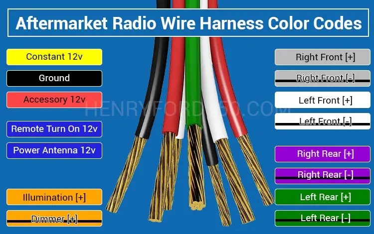
- Yellow Wire – Constant 12v: This is a direct line to the battery, and it supplies most of the power that goes to the radio. It is also a memory backup cable.
- Blue Wire – Remote Turn on 12v & Power Antenna 12v: It triggers the power antenna, antenna amplifier, or factory amplifier.
- Two Green Speaker Wires – Green left rear [+], and Green-Black left rear [-]
- Two Purple Speaker Wires – Purple right rear [+] and Purple-Black right rear [-]
- Black Wire – Ground
- Red Wire – Accessory 12v: This cable gets power when the key is turned to “on.” It triggers the radio to switch on.
- Two White Speaker Wires – White left front [+], and White-Black left front [-]
- Two Gray Speaker Wires – Gray right front [+] and Gray-Black right rear [-]
- Orange Wire – Illumination [+]: It is called the dimmer wire in some vehicles. The dimmer wire occasionally appears as “Orange-Black.” Illumination wires stay at 12v-only whether “on” or “off.” The cables referred to as “dimmers” may be able to adjust between 0 and 12 volts as you alter your interior dash lights.
Note: Green-Black, Purple-Black, White-Black, Gray-Black, and Orange-Black wires are cables with black stripes.
Final Thoughts
You must have found the diagram you are looking for in my extensive Ford F150 radio wiring harness diagram selection if it is within the 7th-14th generation range. It is advisable not to go ahead with a DIY stereo rewiring if you are not adequately skilled in performing such installations.
thank you so very much you guys just made my day